Search filter
917 results found
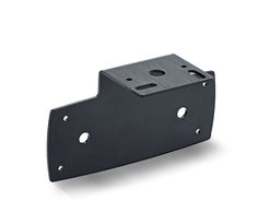
GC 308 installation bracket
For attaching the sensor to the ceiling
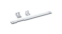
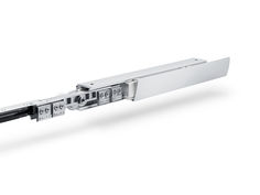
Frame installation set
… installation of the Power lock locking drive
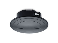
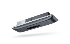
GC 308 ceiling installation kit
… Installation kit for integrating the detector in the ceiling
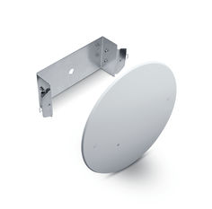
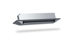
Ceiling installation kit GC 302
… Installation kit for attaching the detector to the ceiling
Ceiling installation kit GC 363 / GC 339
… Installation kit for attaching the detector to the ceiling
Ceiling installation kit GC 365 / GC 341
… Installation kit for attaching the detector to the ceiling
Perlan 140 wood wall installation
… installation
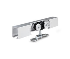
Perlan 140 wood ceiling installation
Sliding door fitting system for timber, plastic, or metal doors with a leaf weight of 140 kg
Levolan 120 glass ceiling installation
… installation
Levolan 60 glass ceiling installation
… installation