Search filter
20 results found
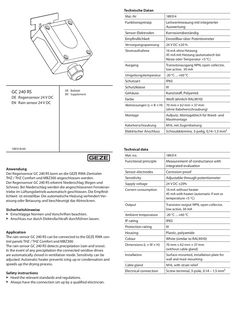
Beiblatt Regensensor GC 240 RS
… Beiblatt EN Supplement 189318-00 Anwendung Der Regensensor GC 240 RS kann an die GEZE RWA-Zentralen THZ / THZ Comfort und MBZ300 angeschlossen werden. Der Regensensor GC 240 RS erkennt Niederschlag (Regen und Schnee). Bei Niederschlag werden die angeschlossenen Fensteran triebe im Lüftungsbetrieb automatisch geschlossen. Die Empfind lichkeit ist einstellbar. Die automatische Heizung verhindert Ver eisung oder Betauung und beschleunigt das Abtrocknen. Sicherheitshinweise XX Einschlägige Normen und Vorschriften beachten. XX Anschluss nur durch Elektrofachkraft durchführen lassen. Application The rain sensor GC 240 RS can be connected to the GEZE RWA control panels THZ / THZ Comfort and MBZ300. The rain sensor GC 240 RS detects precipitation (rain and snow). In the event of any precipitation the connected window drives are automatically closed in ventilation mode. Sensitivity can be adjusted. Automatic heater prevents icing up or condensation and speeds up the drying process. Safety instructions XX Heed the relevant standards and regulations. XX Always have the connection set up by a qualified electrician. Mat.-Nr 189314 Funktionsprinzip Leitwertmessung mit integrierter Auswertung Sensor-Elektroden Korrosionsbeständig Empfindlichkeit Einstellbar über Potentiometer Versorgungsspannung 24 V DC ±20 % Stromaufnahme 16 mA ohne Heizung 45 mA mit Heizung (automatisch bei Nässe oder Temperatur <5 °C) Ausgang Transistorausgang NPN, open collector, low active, 30 mA Umgebungstemperatur -20 °C ... +60 °C Schutzart IP65 Schutzklasse III Gehäuse Kunststoff, Polyamid Farbe Weiß (ähnlich RAL9010) Abmessungen (L × B × H) 70 mm × 62 mm × 37 mm (ohne Kabelverschraubung) Montage Aufputz, Montageblech für Wand- und Mastmontage Kabelverschraubung M16, mit Zugentlastung Elektrischer Anschluss Schraubklemme, 3-polig, 0,14–1,5 mm² Technical data Mat. no. 189314 Functional principle Measurement of conductance with integrated evaluation Sensor electrodes Corrosion-proof Sensitivity Adjustable through potentiometer Supply voltage 24 V DC ±20% Current consumption 16 mA without heater 45 mA with heater (automatic if wet or temperature <5 °C) Output Transistor output NPN, open collector, low active, 30 mA Ambient temperature -20 °C ... +60 °C IP rating IP65 Protection rating III Housing Plastic, polyamide Colour White (similar to RAL9010) Dimensions (L × W × H) 70 mm × 62 mm × 37 mm (without cable gland) Installation Surface-mounted, installation plate for wall and mast mounting Cable gland M16, with strain relief Electrical connection Screw terminal, 3-pole,
(PDF | 156 KB)
Beiblatt TSA 160 NT Austauscheinheit
… Beiblatt EN Supplementary sheet Austria GEZE Austria E-Mail: austria.at@geze.com www.geze.at Baltic States – Lithuania / Latvia / Estonia E-Mail: baltic-states@geze.com Benelux GEZE Benelux B.V. E-Mail: benelux.nl@geze.com www.geze.be www.geze.nl Bulgaria GEZE Bulgaria - Trade E-Mail: office-bulgaria@geze.com www.geze.bg China GEZE Industries (Tianjin) Co., Ltd. E-Mail: chinasales@geze.com.cn www.geze.com.cn Romania GEZE Romania S.R.L. E-Mail: office-romania@geze.com www.geze.ro GEZE Industries (Tianjin) Co., Ltd. Branch Office Shanghai E-Mail: chinasales@geze.com.cn www.geze.com.cn Russia OOO GEZE RUS E-Mail: office-russia@geze.com www.geze.ru GEZE Industries (Tianjin) Co., Ltd. Branch Office Guangzhou E-Mail: chinasales@geze.com.cn www.geze.com.cn Scandinavia – Sweden GEZE Scandinavia AB E-Mail: sverige.se@geze.com www.geze.se GEZE Industries (Tianjin) Co., Ltd. Branch Office Beijing E-Mail: chinasales@geze.com.cn www.geze.com.cn Scandinavia – Norway GEZE Scandinavia AB avd. Norge E-Mail: norge.se@geze.com www.geze.no France GEZE France S.A.R.L. E-Mail: france.fr@geze.com www.geze.fr Scandinavia – Denmark GEZE Danmark E-Mail: danmark.se@geze.com www.geze.dk Hungary GEZE Hungary Kft. E-Mail: office-hungary@geze.com www.geze.hu Singapore GEZE (Asia Pacific) Pte, Ltd. E-Mail: gezesea@geze.com.sg www.geze.com Iberia GEZE Iberia S.R.L. E-Mail: info.es@geze.com www.geze.es South Africa GEZE South Africa (Pty) Ltd. E-Mail: info@gezesa.co.za www.geze.co.za India GEZE India Private Ltd. E-Mail: office-india@geze.com www.geze.in Switzerland GEZE Schweiz AG E-Mail: schweiz.ch@geze.com www.geze.ch Italy GEZE Italia S.r.l. Unipersonale E-Mail: italia.it@geze.com www.geze.it Turkey GEZE Kapı ve Pencere Sistemleri E-Mail: office-turkey@geze.com www.geze.com GEZE Engineering Roma S.r.l E-Mail: italia.it@geze.com www.geze.it Ukraine LLC GEZE Ukraine E-Mail: office-ukraine@geze.com www.geze.ua Korea GEZE Korea Ltd. E-Mail: info.kr@geze.com www.geze.com Poland GEZE Polska Sp.z o.o. E-Mail: geze.pl@geze.com www.geze.pl 194935-00 Werkzeuge àà àà àà àà Inbus
(PDF | 1 MB)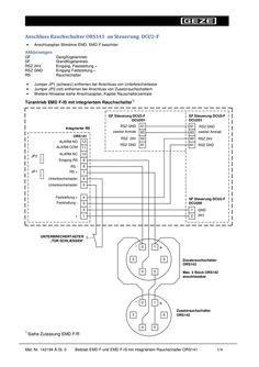
Installation instructions, Supplement EMD F and EMD F-IS with integrated smoke switches ORS141
… Beiblatt EMD F und EMD F-IS mit integriertem Rauchschalter ORS141 1/4 *) Türantrieb EMD F mit integriertem Rauchschalter Steuerung DCU2-F DCU201 Integrierter RS ORS141 JP2 61 RSZ GND 63 zweiter Antrieb 62 RSZ 24V 61 RSZ GND ALARM NO 12 ALARM COM 11 ALARM NC 10 Eingang RS … Beiblatt EMD F und EMD F-IS mit integriertem Rauchschalter ORS141 2/4 Connection of smoke switch ORS141 to control unit DCU2-F • Observe the wiring diagram Slimdrive EMD, EMD F Abbreviations GF SF RSZ 24V RSZ GND RS • • • Active leaf drive Fixed leaf drive Input, hold-open + Input, hold-open – Smoke switch Remove Jumper JP1 (black) if circuit breaker is connected Remove Jumper JP2 (red) if additional smoke switches are connected For additional information, see wiring diagram, chapter Smoke switch control unit Door drive EMD F-IS with integrated smoke switch *) GF control unit DCU2-F DCU201 Integrated RS ORS141 ALARM NO 12 JP2 JP1 SF control unit DCU2-F DCU201 RSZ GND 61 61 RSZ GND Second drive 63 63 Second drive RSZ 24V 62 62 RSZ 24V RSZ GND 61 61 RSZ GND ALARM COM 11 ALARM NC 10 Input RS
(PDF | 53 KB)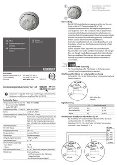
140521_01_Deckentemperaturmelder_GC_163_DE_GB.pdf
… Beiblatt GB Supplement DIBt-Zulassung àà Für Feststellanlagen für Abschlüsse in Rettungswegen müssen Rauchmelder eingesetzt werden. Abschlusswiderstände zur Leitungsüberwachung Tel.: 0049 7152 203-0 Fax: 0049 7152 203-310 140521-01 www.geze.com Im Sockel GC 160 B ist der Widerstand zur Leitungsüberwachung bereits eingebaut. GC 160 B Deckentemperaturmelder GC 163 EN 54-5 EN 14637 24 V 6,8 kΩ GND Dokument FA GC 160 - Anleitung zur Montage, Inbetriebnahme, Bedienung und Wartung beachten, Mat. Nr. 141513. Rückseite des Sockels Technische Daten Temperaturmelder GC 163 mit àà Temperaturmelder GC 003 D àà Sockel GC 160 B Temperaturmelder GC 003 D Farbe Abmessungen (mit Sockel, DxH) Funktionsprinzip Alarmtemperatur EN 54-5 Klasse Eingangsspannung Eingangsstrom Einbaulage Umgebungstemperatur Alarmwiderstand Stromerhöhungsprinzip - kein Alarm - Alarm Abschlusswiderstände Meldertest Mat. Nr. 139883 Signalisierung LED Mat. Nr. 141459 weiß, RAL 9010 110 mm x 54 mm Alarm, falls Umgebungstemperatur die Alarmtemperatur überschreitet oder falls sich die Umgebungstemperatur sehr schnell erhöht, selbstrückstellend 57°C A1R 24 V DC maximal 10 mA Deckenmontage -30°C bis 70°C 2,2 kW … Use GC 163 GB Ceiling temperature sensor DE Deckentemperaturmelder GB Supplement DE Beiblatt The GC 163 is a ceiling temperature sensor for use in the GEZE hold-open device FA GC 160. Temperature sensor measures the ambient temperature and respond if the temperature exceeds a predetermined maximum value or increases dramatically within a certain time. This temperature sensor operates according to the current increase principle. In the event of an alarm, the current consumption of the sensor changes. Usually smoke and fumes spread quickly in case of a fire. The rise in temperature occurs only after a delay. Smoke detectors should generally be used for hold-open devices as far as possible. In areas with interferences such as steam, dust, condensation or operation-related smoke emissions (workshops, kitchens), it makes more sense to use temperature sensors instead of smoke detectors. DIBt-approval àà Smoke detectors must be used in hold-open devices for closures on escape routes. Termination resistors for line monitoring GEZE GmbH Reinhold-Vöster-Straße 21–29 71229 Leonberg Germany The resistor for line monitoring is already installed in the base GC 160 B. Tel.: 0049 7152 203-0 Fax: 0049 7152 203-310 140521-01 www.geze.com GC 160 B 24 Ceiling temperature sensor GC 163 V 6,8 kΩ GND EN 54-5 EN 14637 Document FA GC 160 - Observe instructions for installation, commissioning, operation and maintenance, Mat. No. 141515. Signalling Technical data Temperature sensor GC 163 with Mat. No. 139883 àà Temperature sensor GC 003 D àà Base GC 160 B Temperature sensor GC 003 D Colour Dimensions (with base, DxH) Functional principle Alarm temperature EN 54-5 Class Input voltage Input current Installation position Ambient temperature Alarm resistance Current increase principle - No alarm - Alarm Termination resistors Detector test Back of the base Mat. No. 141459 white, RAL 9010 110 mm x 54 mm Alarm if ambient temperature exceed the alarm temperature or if the ambient temperature increases very rapidly, self-resetting 57°C A1R 24 V DC Maximum 10 mA Ceiling mounting -30°C to 70°C
(PDF | 429 KB)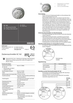
141482_01_Deckenrauchmelder_GC_162_DE_GB.pdf
… Beiblatt GB Supplement Schutz des Rauchmelders vor Verschmutzung àà Die Staubschutzkappe des Rauchmelders erst bei der Inbetriebnahme entfernen. àà Nach Einbau des Rauchmelders und Entfernung des Staubschutzes darauf achten, dass kein Staub in die Messkammer gelangt. Dies führt zu einer erhöhten Verschmutzung und kann die Lebensdauer des Rauchmelders erheblich verkürzen. àà Die Messkammer eines Rauchmelders darf nicht geöffnet werden. Abschlusswiderstände zur Leitungsüberwachung GEZE GmbH Reinhold-Vöster-Straße 21–29 71229 Leonberg Germany Im Sockel GC 160 B ist der Widerstand zur Leitungsüberwachung bereits eingebaut. Tel.: 0049 7152 203-0 Fax: 0049 7152 203-310 141482-01 www.geze.com GC 160 B 24 Deckenrauchmelder GC 162 V GND EN 54-7 EN 14637 Dokument FA GC 160 - Anleitung zur Montage, Inbetriebnahme, Bedienung und Wartung beachten, siehe www.geze.com Mat. Nr. 141513. 6,8 kΩ Rückseite des Sockels Signalisierung Technische Daten Deckenrauchmelder GC 162 mit àà Rauchmelder GC 002 D àà Sockel GC 160 B Rauchmelder GC 002 D Farbe Abmessungen (mit Sockel, DxH) Funktionsprinzip Insektengitter Eingangsspannung Eingangsstrom Einbaulage Umgebungstemperatur Alarmwiderstand Stromerhöhungsprinzip - kein Alarm - Alarm Abschlusswiderstände Meldertest LED Mat. Nr. 139882 Mat. Nr. 141458 weiß, RAL 9010 110 mm x 54 mm Streulicht, Alarmschwellennachführung selbstrückstellend verhindert das Eindringen von Insekten in die Messkammer 24 V DC maximal 10 mA Deckenmontage -30°C bis 70°C 2,2 kW … Use GC 162 GB Ceiling smoke detector DE Deckenrauchmelder GB Supplement DE Beiblatt The GC 162 is a ceiling smoke detector for use in the GEZE holdopen device FA GC 160. Smoke detectors recognise smoke. They operate on the principle of diffused light. A light emitter and a light receiver are arranged in the measuring chamber in such a way that normally no light falls on the receiver. If there are suspended particles (smoke) in the measuring chamber, this scatters a portion of the light on the receiver, which converts it into an electrical signal. This smoke detector operates according to the current increase principle. In the event of an alarm, the current consumption of the detector changes. A smoke detector recognises not only smoke, but also all other suspended particles and is sensitive to pollution. Protection of the smoke detector against dirt accumulation GEZE GmbH Reinhold-Vöster-Straße 21–29 71229 Leonberg Germany àà Remove the dust cover of the smoke detector only at the time of the initial operation. àà After the installation of the smoke detector and removal of the dust cover, ensure that dust does not enter the measuring chamber. Otherwise it may result in increased dust accumulation that can significantly shorten the service life of the smoke detector. àà The measuring chamber of a smoke detector should not be opened. Termination resistors for line monitoring Tel.: 0049 7152 203-0 Fax: 0049 7152 203-310 141482-01 www.geze.com The resistor for line monitoring is already installed in the base GC 160 B. GC 160 B Ceiling smoke detector GC 162 24 EN 54-7 EN 14637 V 6,8 kΩ GND Document FA GC 160 - Observe instructions for installation, commissioning, operation and maintenance, see www.geze. com - Mat. No. 141515. Technical data Ceiling smoke detector GC 162 with àà Smoke detector GC 002 D àà Base GC 160 B Smoke detector GC 002 D Colour Dimensions (with base, DxH) Functional principle Insect screen Input voltage Input current Installation position Ambient temperature Alarm resistance Current increase principle - No alarm - Alarm Termination resistors Detector test Mat. No. 139882 Mat. No. 141458 white, RAL 9010 110 mm x 54 mm Diffused light, alarm threshold tracking, self-resetting prevents insects from entering the measuring chamber 24 V DC Maximum 10 mA Ceiling mounting -30°C to 70°C
(PDF | 424 KB)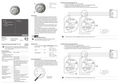
140493_00_Deckentemperaturmelder_ceiling temperature detector_GC_153 DE_EN.pdf
… Beiblatt GB Supplement Tel.: 0049 7152 203-0 Fax: 0049 7152 203-310 www.geze.com Magnetsensor zum Testen (hinter GEZE Logo) LED zur Zustandsanzeige Anschluß an Sturzrauchschalter ORS 141 XX Jumper J2 (rot) abziehen (= mit Deckenmelder). XX Widerstände im Sockel des ersten Deckenmelders trennen . XX Im Sockel des letzten Deckelmelders eine Drahtbrücke zwischen 24V und ASin einbauen XX Kabeltyp J-Y(ST)Y, 2x2x0,8 mm2 verwenden. Länge maximal 15m. . ASin Abschlusswiderstände Im Relaissockel GC 150 B sind Widerstände bereits eingebaut. Über eine Sollbruchstelle können die Widerstände getrennt werden. Dazu einen Schraubendreher … 2 Use GC 153 GB Ceiling temperature sensor DE Deckentemperaturmelder GB Supplement DE Beiblatt Magnetic sensor for testing (behind GEZE logo) LED for status indication Connection to the lintel smoke switch GC 151 XX Remove the red jumper J2 (= with ceiling detector). XX Set jumper J3 to the measuring chamber (Pin 2-3, = with line monitoring). XX Disconnect the resistors in the base of the first ceiling detector . XX Use cabel type J-Y(ST)Y, 2x2x0,6 mm2 or 2x2x0,8 mm2. Maximum length less than 15 m. The GC 153 is a ceiling temperature sensor for use in the GEZE hold-open device FA GC 150. Temperature sensor measures the ambient temperature. If the temperature exceeds a predetermined maximum value or the temperature increases very strongly within a certain period, then the potential free alarm output (relay) of the temperature sensor opens. Usually smoke and fumes spread quickly in case of a fire. The rise in temperature occurs only after a delay. Smoke detectors should generally be used for hold-open devices as far as possible. In areas with interferences such as steam, dust, condensation or operation-related smoke emissions (workshops, kitchens), it makes more sense to use temperature sensors instead of smoke detectors. 15 mA AS Ceiling detector (additional sensor) GND Reference potential (ground) DIBt-certification GEZE GmbH P.O.Box 1363 71229 Leonberg Germany Tel.: 0049 7152 203-0 Fax: 0049 7152 203-310 www.geze.com Smoke detectors must be used in hold-open devices for closures on escape routes. must be disconnected. 140493-00 Ceiling temperature sensor GC 153 EN 54-5 EN 14637 Document FA GC 150 - Observe instructions for installation, commissioning, operation and maintenance, see www.geze. com - Mat. No. 141512. Signalling LED Without voltage Ceiling temperature sensor GC 153 with àà Temperature sensor GC 003 D àà Relay base GC 150 B Temperature sensor GC 003 D Colour Dimensions (with base, DxH) Mat. No. 139881 Functional principle Alarm temperature EN 54-5 Class Alarm if ambient temperature exceeds the alarm temperature or if the ambient temperature increases very rapidly, Self-resetting 57°C A1R Input voltage 24 V DC Input current Installation position Ambient temperature Alarm output Maximum 20 mA Ceiling mounting -30°C to 70°C Potential free relay output, NCC maximum 24 V DC / maximum
(PDF | 681 KB)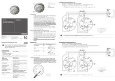
141474_01_Deckenrauchmelder_GC_152_DE_GB.pdf
… Beiblatt GB Supplement Schutz des Rauchmelders vor Verschmutzung àà Die Staubschutzkappe des Rauchmelders erst bei der Inbetriebnahme entfernen. àà Nach Einbau des Rauchmelders und Entfernung des Staubschutzes darauf achten, dass kein Staub in die Messkammer gelangt. Dies führt zu einer erhöhten Verschmutzung und kann die Lebensdauer des Rauchmelders erheblich verkürzen. àà Die Messkammer des Rauchmelders darf nicht geöffnet werden. Tel.: 0049 7152 203-0 Fax: 0049 7152 203-310 www.geze.com 141474-01 Deckenrauchmelder GC 152 EN 54-7 EN 14637 Dokument FA GC 150 - Anleitung zur Montage, Inbetriebnahme, Bedienung und Wartung beachten, siehe www. geze.com - Mat. Nr. 141511. Technische Daten Deckenrauchmelder GC 152 mit àà Rauchmelder GC 002 D àà Relaissockel GC 150 B Rauchmelder GC 002 D Farbe Abmessungen (mit Sockel, DxH) Funktionsprinzip Insektengitter Eingangsspannung Eingangsstrom Einbaulage Umgebungstemperatur Alarmausgang Abschlusswiderstände Meldertest Mat. Nr. 139850 Mat. Nr. 141458 weiß, RAL 9010 110 mm x 67 mm Streulicht, Alarmschwellennachführung, selbstrückstellend verhindert das Eindringen von Insekten in die Messkammer 24 V DC maximal 20 mA Deckenmontage -30°C bis 70°C potentialfreier Relaisausgang, Öffner maximal 24 V DC / maximal … 2 Magnetic sensor for testing (behind GEZE logo) LED for status indication Connection to the lintel smoke switch GC 151 XX Remove the red jumper J2 (= with ceiling detector). XX Set jumper J3 to the measuring chamber (Pin 2-3, = with line monitoring). XX Disconnect the resistors in the base of the first ceiling detector . XX Use cabel type J-Y(ST)Y, 2x2x0,6 mm2 or 2x2x0,8 mm2. Maximum length less than 15 m. connection box Use GC 152 GB Ceiling smoke detector DE Deckenrauchmelder GEZE GmbH Reinhold-Vöster-Straße 21–29 71229 Leonberg Germany GB Supplement DE Beiblatt Protection of the smoke detector against dirt accumulation àà Remove the dust cover of the smoke detector only at the time of the initial operation. àà After the installation of the smoke detector and removal of the dust cover, ensure that dust does not enter the measuring chamber. Otherwise it may result in increased dust accumulation that can significantly shorten the service life of the smoke detector. àà The measuring chamber of the smoke detector should not be opened. Tel.: 0049 7152 203-0 Fax: 0049 7152 203-310 www.geze.com 141474-01 Ceiling smoke detector GC 152 EN 54-7 EN 14637 Document FA GC 150 - Observe instructions for installation, commissioning, operation and maintenance, see www.geze. com - Mat. No. 141512. Technical data Ceiling smoke detector GC 152 with àà Smoke detector GC 002 D àà Relay base GC 150 B Smoke detector GC 002 D Colour Dimensions (with base, DxH) Functional principle Insect screen Input voltage Input current Installation position Ambient temperature Alarm output Termination resistors Detector test The GC 152 is a ceiling smoke detector for use in the GEZE hold-open device FA GC 150. Smoke detectors recognise smoke. They operate on the principle of diffused light. A light emitter and a light receiver are arranged in the measuring chamber in such a way that normally no light falls on the receiver. If there are suspended particles (smoke) in the measuring chamber, this scatters a portion of the light on the receiver, which converts it into an electrical signal. The potential-free alarm output (relay) opens the smoke detector. A smoke detector recognises not only smoke, but also all other suspended particles and is sensitive to pollution. Mat. No. 139850 Mat. No. 141458 white, RAL 9010 110 mm x 67 mm Diffused light, alarm threshold tracking, self-resetting prevents insects from entering the measuring chamber 24 V DC Maximum 20 mA Ceiling mounting -30°C to 70°C Potential free relay output, NCC maximum 24 V DC / maximum
(PDF | 688 KB)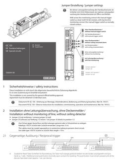
Supplementary sheet special circuits GC 151
… Beiblatt GB Supplement mit Deckenmelder / with ceiling-mounted alarm ohne Leitungsüberwachung / without line monitoring mit Leitungsüberwachung / with line monitoring Jumper gesetzt / Jumper set 156644-00
(PDF | 588 KB)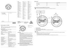
Wiring diagram heat detector GC 163 RWA
… Beiblatt GC 163 RWA +
(PDF | 5 MB)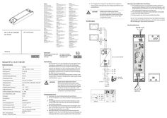
NT … A-24 V SM DIR
… Beiblatt unbedingt gelesen werden. XX Einschlägige Normen und Vorschriften beachten, insbesondere DIN VDE 0100-600 oder die länderspezifischen Vorschriften beachten. XX Als netzseitige Trennvorrichtung einen bauseitigen 2-poligen Leistungsschutzschalter (Überspannungskat. III) mit Verrieglungsmöglichkeit verwenden. XX Nach dem Einbau muss der gesamte Klemmenbereich abgedeckt sein. Nur so ist das Gerät ausreichend gegen unzulässiges Berühren spannungsführender Teile geschützt. 230V AC L1i L2h N 230 V AC 24V A 24V B Signal LIN 230V AC GND +24V L1-N +24V GND L2-N DANGER! Danger of electric shock! Before working on the electrical system interrupt the power supply, secure it against being switched on again and verify the safe isolation from supply. Wiring diagram Notes on electrical connection: XX The cabling must be carried out in such a way that there is sufficient clearance (> 20 mm) between input and output line and the power line and output line are laid separately XX Always use wire-end ferrules for wire cores XX Insulate wires that are not used XX Wiring diagram of the 24V window drives has to be considered. At 24 V DC and with long supply cable, the cable must have a sufficiently large cross-section to prevent voltage drop. Calculate cross-section! Connection terminals 24 V DC, 2,5 A ∓ ± EN Wiring diagram NT 2,5 A-24 V SM DIR EN Power supply NT 2,5 A-24 V SM DIR 230V AC 195297-01 NT 2,5 A-24 V SM DIR power supply Technical data ID 195293 Mains voltage 220 - 240 V AC +/-10% Mains frequency 50-60 Hz Input current 0,58 A Idling input power 0,24 W Output power 60 W Output voltage 24 V DC ±5% (SELV) Output current 2,5 A, ED 30%,
(PDF | 1 MB)